|
grandMA3 User Manual » Fixture Types » Build Fixture Types » Link Models to Geometries
|
Version 2.1
|
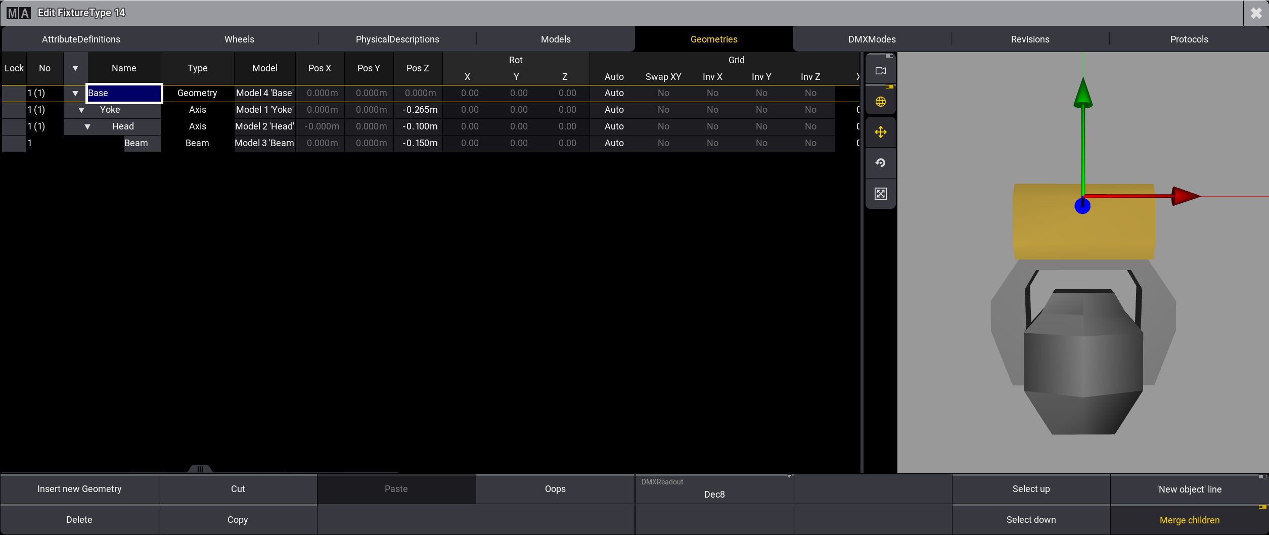
To correctly display the models in the 3D Viewer, the next thing to do is to link models to geometries.
Requirement:
- Tap the tab Geometries.
- To link the model Base to geometries, tap, and hold the cell in the column Model.
- Pop-up Select Model opens.
- Select Base.
- Set the offset of position in single geometries.
- In Base, leave the default value of Pos Z.
- In Yoke, set Pos Z to -0.265 m.
- In Head, set Pos Z to -0.100 m.
- In Beam, set Pos Z to -0.150 m.
|
|
Hint: |
|
The offset of the position depends on the measurements of the models.
|
|
|
Hint: |
|
These cells can also be edited using the Geometry
Viewer.
|
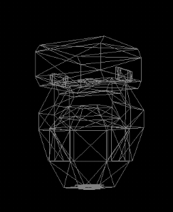
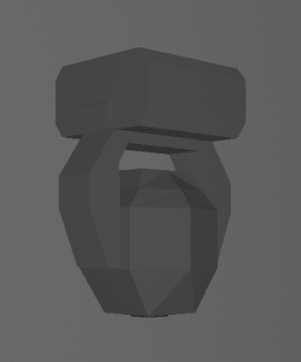
This is the result in the 3D window.
|
|
Hint: |
|
To display the basic moving head in wireframe in the 3D window, see 3D topic.
|
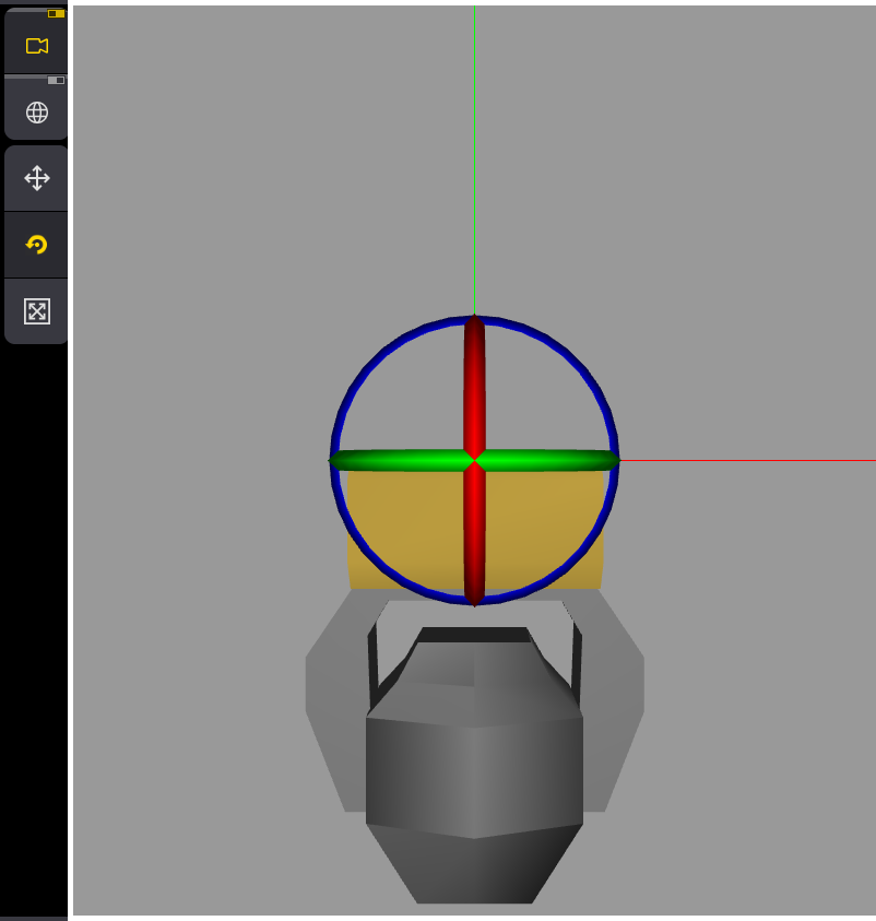
Geometry Viewer
The geometry viewer on the right side of the window displays a real time 3D visualization of the selected geometry tree.
|
|
Hint: |
|
To display the geometries in the geometry viewer, add meshes in the models tab first.
See Insert Models.
|
-
Tap on the part of the fixture you want to edit or select a geometry in the table.
This part is now selected and is displayed with a yellow color in the 3D area. -
Tap and hold one of the colored indicators to move, scale or rotate the geometries.
The corresponding cells change accordingly.
![]() (Camera
focus):
(Camera
focus):
If this button is enabled, the selected geometry is displayed in the center of the 3D area.
If this button is disabled, the center of the whole fixture is pinned to the center of the 3D
area.
![]() (World
model
transformation):
(World
model
transformation):
If this button is enabled, the axis follows the world.
If this button is disabled, the axis follows the selected geometry.
![]() (Translation
mode):
(Translation
mode):
Lets you move the selected geometry.
Tap and hold the arrow of the selected axis and move it. When the geometry is in the desired
position,
release
your finger.
![]() (Rotation mode):
(Rotation mode):
Lets you rotate the selected geometry.
Tap and hold one of the colored rings and move it. When the geometry is in the desired position,
release
your
finger.
While you rotate the geometry along its own axis, the degree value of the rotation is displayed
in the top
left corner of the 3D area. Additionally, a colored disc shows a visual representation of
the angle by
which the geometry is rotated.
![]() (Scale
mode):
(Scale
mode):
Lets you scale the selected geometry.
Tap and hold one of the axis indicators and move it. When the geometry has the desired size,
release your
finger.
To scale all three axes at the same time, tap and move the block in the center of the axis
indicators.
|
|
Hint: |
|
Scaling the geometries changes the values for length, width, and hight in the Models tab.
|
|
|
Hint: |
|
If you scale a geometry whose model is also linked to other geometries, those
geometries are scaled
as
well.
|
This is important for fully and accurately managing your fixture type.