

- grandMA2 User Manual
- grandMA3 Mode2
- grandMA2 Quick Start Guide
- grandMA2 Quick Manual onPC solutions
- MA 3D
- MA VPU
- Introduction
- Help from MA technical support
- System requirements
- For your Safety
- Functions and Features
- Transition from grandMA video to MA VPU
- Teaser Mode
- Comparison VPU plus / VPU basic / VPU light
- Main Features
- Installation and Maintenance
- Startup
- Software update
- Service Packs
- Update of Fixture Types
- Backup
- Handling backups with the VPU
- Start Acronis on VPUs with serial Numbers up to # 86 on
- Start Acronis on VPUs with serial Numbers from # 87
- Restoring an image with Acronis
- Storing an image with Acronis
- Backup the VPU content after shipment
- Access VPU via Network
- Version of grandMA desk or grandMA onPC (off-line)
- IP Addresses
- IP Address of the PC
- Art-Net IP Address
- EDID Manager
- CITP / MSEX Protocol
- Installation and Maintenance
- Communication with the grandMA Desk Series
- Connection with the grandMA desk
- Connection with the grandMA onPC (off-line) software
- Connection States
- Data Management
- Master slave
- Principle function diagram
- Layer Properties
- Layer Reference
- Virtual Outputs
- Virtual Output: Configuration of a TripleHead2Go Digital Port
- Predefined Constellation
- Several MA VPU applications in one grandMA show
- Quickstart with grandMA2
- Program surface
- Internal Touch-Screen VPU plus
- Internal Screen VPU light
- Menu Bar
- File...
- View...
- Render...
- Help...
- Toolbar
- Status Bar
- Preview
- Multi Preview
- Content Editor
- Content: Image Pool (I-Pool)
- Content: Text Ticker
- Content: Eff1 Type...Eff4 Type
- Content: 3D Objects
- Content: Mask
- Warper
- Warper Fullscreen View
- Warper Basic Operation
- Warping
- File Browser
- Features Attributes and Functions
- Order of Effect Execution
- Softedging
- Keystoning
- Pixel Mapper
- VPU - Pixel Mapper Graphical View
- Pixel Mapper Toolbar
- Pixel Mapper Editor
- VPU - Pixel Mapper Grid View
- Console - VPU Pixel Mapper View
- VPU - Pixel Mapper Graphical View
- Creation of customized 3D Objects
- Content Specifications
- Rovi Total CodeStudio for converting your content into MPEG2
- Hap Content Converter
- Warnings
- Keyboard Shortcuts
- FAQ and Troubleshooting
- Supplement MA Lighting
- Intended use
- Data
- Symbols and warning labels
- LIMITATIONS
- Transport
- General Safety Instructions
- IMPORTANT SAFETY INSTRUCTIONS
- Electric shock warning on the rear of the grandMA
- Safety and Environment
- Quickstart Connect VPU plus
- Quickstart Connect VPU light
- Switching the apparatus On/Off
- Maintenance
- Conformity
- Introduction
- Release Notes
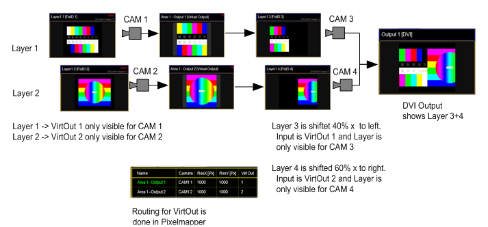
Virtual Outputs
The Pixel Mapper Output can be configured with a "Virtual Output ID". You should not place any Pixel Mapper Fixtures onto that Pixel Mapper Output. If a Virtual Output ID is set, then any "Render IP" settings are ignored, the field is greyed out. The idea behind that: since a Virtual Output can be assigned with a dedicated, single Camera, you can route certain Layers to this dedicated Camera. So these Layers are only displayed on that Camera and thus only rendered on the Pixel Mapper Output. You can route as many Layers to that Virtual Output as you like. The next step is to route this Virtual Output as Virtual Input onto another Layer. This Layer is only displayed on a Camera that is only visible on a DVI Ouput.
Example for 2 Virtual Outputs:
What is it good for?
The user can create output display arrangements where each single arrangement is controlled by a Camera. So each single arrangement layer can be modified via the softedge, keystone and splitscreen parameters of each Camera. This comes in handy if an LED controller grabs certain areas out of the displayed picture and the VPU user wants to control these areas with a dedicated VPU Camera Fixture. This can be used to drive a “Matrox Triple Head to Go” setup and control each DVI Output with a dedicated VPU Camera Fixture. The “Triple Head to Go Device” is recognized by the VPU Software as one big output. What you basically do is to assign 3 Layers that display Virtual Output 1; 2 and 3 next to each other.