
- grandMA2 User Manual
- grandMA3 Mode2
- grandMA2 Quick Start Guide
- grandMA2 Quick Manual onPC solutions
- MA 3D
- MA VPU
- Introduction
- Help from MA technical support
- System requirements
- For your Safety
- Functions and Features
- Transition from grandMA video to MA VPU
- Teaser Mode
- Comparison VPU plus / VPU basic / VPU light
- Main Features
- Installation and Maintenance
- Startup
- Software update
- Service Packs
- Update of Fixture Types
- Backup
- Handling backups with the VPU
- Start Acronis on VPUs with serial Numbers up to # 86 on
- Start Acronis on VPUs with serial Numbers from # 87
- Restoring an image with Acronis
- Storing an image with Acronis
- Backup the VPU content after shipment
- Access VPU via Network
- Version of grandMA desk or grandMA onPC (off-line)
- IP Addresses
- IP Address of the PC
- Art-Net IP Address
- EDID Manager
- CITP / MSEX Protocol
- Installation and Maintenance
- Communication with the grandMA Desk Series
- Connection with the grandMA desk
- Connection with the grandMA onPC (off-line) software
- Connection States
- Data Management
- Master slave
- Principle function diagram
- Layer Properties
- Layer Reference
- Virtual Outputs
- Virtual Output: Configuration of a TripleHead2Go Digital Port
- Predefined Constellation
- Several MA VPU applications in one grandMA show
- Quickstart with grandMA2
- Program surface
- Internal Touch-Screen VPU plus
- Internal Screen VPU light
- Menu Bar
- File...
- View...
- Render...
- Help...
- Toolbar
- Status Bar
- Preview
- Multi Preview
- Content Editor
- Content: Image Pool (I-Pool)
- Content: Text Ticker
- Content: Eff1 Type...Eff4 Type
- Content: 3D Objects
- Content: Mask
- Warper
- Warper Fullscreen View
- Warper Basic Operation
- Warping
- File Browser
- Features Attributes and Functions
- Order of Effect Execution
- Softedging
- Keystoning
- Pixel Mapper
- VPU - Pixel Mapper Graphical View
- Pixel Mapper Toolbar
- Pixel Mapper Editor
- VPU - Pixel Mapper Grid View
- Console - VPU Pixel Mapper View
- VPU - Pixel Mapper Graphical View
- Creation of customized 3D Objects
- Content Specifications
- Rovi Total CodeStudio for converting your content into MPEG2
- Hap Content Converter
- Warnings
- Keyboard Shortcuts
- FAQ and Troubleshooting
- Supplement MA Lighting
- Intended use
- Data
- Symbols and warning labels
- LIMITATIONS
- Transport
- General Safety Instructions
- IMPORTANT SAFETY INSTRUCTIONS
- Electric shock warning on the rear of the grandMA
- Safety and Environment
- Quickstart Connect VPU plus
- Quickstart Connect VPU light
- Switching the apparatus On/Off
- Maintenance
- Conformity
- Introduction
- Release Notes
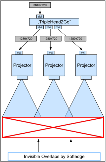
Virtual Output: Configuration of a TripleHead2Go Digital Port
The following example shows the configuration of a TripleHead2Go Digital DisplayPort in 3xHD:
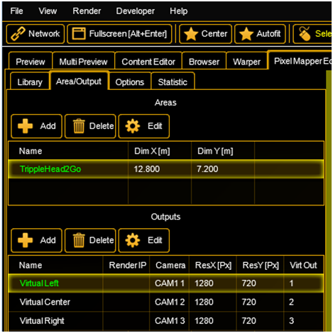
Inside the Pixelmapper Setup
- First step is to create an ”Area“ (see figure below). It’s helpful to use the same ratio when applying values for the dimensions as they will be used for the “Virtual Outputs“ - in this case e.g. 12.8 x 7.2 meters. It actually matters only for the visualization inside the Pixelmapper and has no influence to the final output
- Next step is to create inside the area “TripleHead2Go” Digital three “Virtual Outputs” each with a resolution of 1280x720. Next is the assignment of IDs for the "Virtual Outputs", (column “Virt Out”, e.g. 1..3) and for the cameras (column Camera, e.g. 1..3). When a "Virtual Output ID" was entered the entry inside the column RenderIP of the same line will be automatically removed as no pixelmapper is to be used together with this output. The "Virtual Output ID" is important for mapping to layers. The individual attributes of the “Virtual Outputs” (e.g. Softedge) can be adjusted by selecting the proper camera by “Camera ID”.
- The complete content which will finally range over all three displays will be played back using e.g. “Layer 1” with a resolution of e.g. 3712x720.
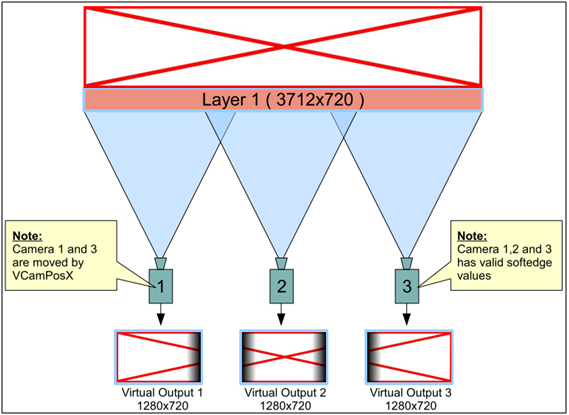
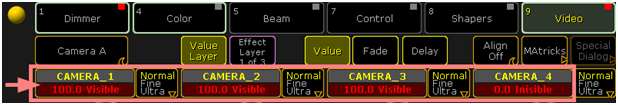
- Layer 1 will be parameterized in a way (using a MA Lighting console or onPC) that it is only visible for Camera 1, 2 and 3 (which are already linked with the corresponding “Virtual Outputs”).
- Camera 1 and 3 will be shifted in a way to only show the wanted selection by using VCamPosX.
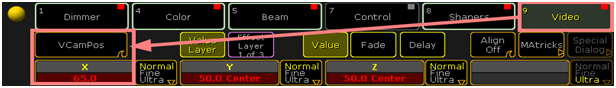
- The Softedge Parameter needs to be properly adjusted from the console or onPC software (Example for Camera 1, which is assigned to left part of the image)
- Provided Softedge is adjusted correctly the Camera Layer display of the VPU looks now like this:
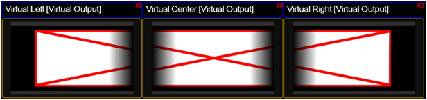
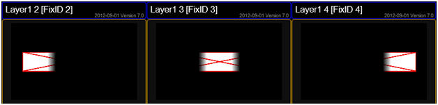
Inside the Multipreview the “Virtual Outputs” are displayed in the following way: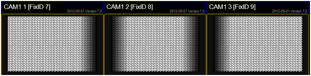
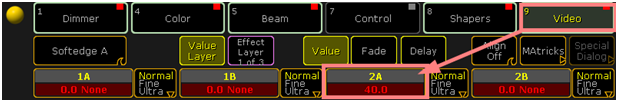
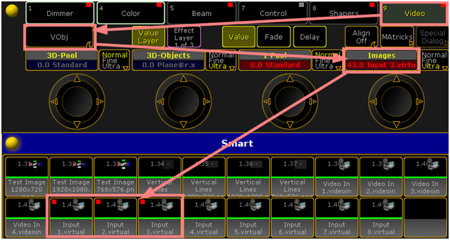
- Layer 2, 3 and 4 (referring to the figure below) are the carrier to apply the content of the virtual Outputs 1-3 via the channelsets "Virtual Input 1-3" . Layer 2 receives its input from the virtual Output 1 via the virtual Input 1. Respectively Layer 3 receives its input virtual Output 2 via the virtual Input 2. Analog the same is true for Layer 4 and virtual Output 3.
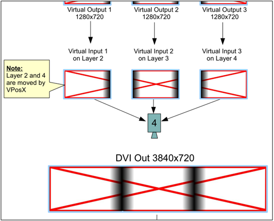
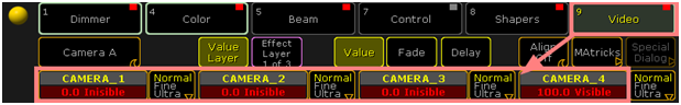
- Layer 2, 3 and 4 are parameterized to be only visible by Camera 4. Camera 4 is assigned to the physical DVI output of the VPU.
- The position of Layer 2 and 4 can be shifted by using the VPosX parameter.
The Multipreview display of the Layer 2-4: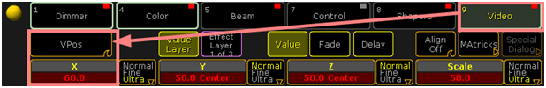
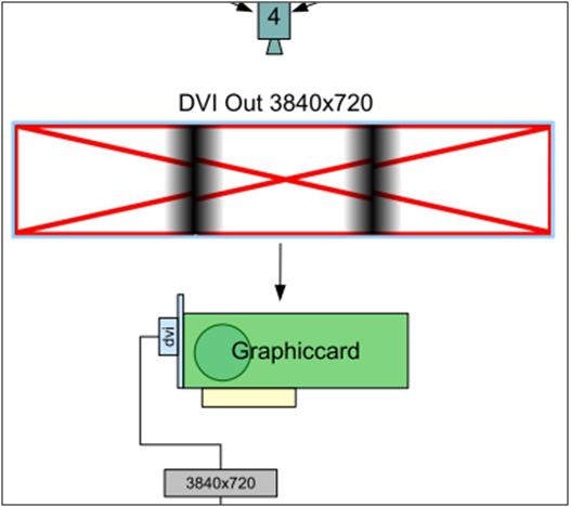
- The actual output at the DVI connector is shown below:
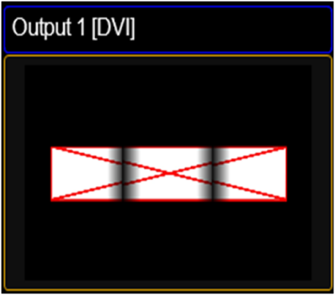
- The TripleHead2Go splits this signal into three independent single pictures. When send to three projectors and taken the soft edged overlap into account the complete images on the canvas looks like one big.