

- grandMA3 User Manual
- grandMA3 Quick Start Guide
- 00 Welcome
- 01 New Show and Setup
- 02 First Patch
- 03 First View Setup
- 04 Control Simple Fixtures
- 05 3D Fixture Setup
- 06 Groups
- 07 Appearance
- 08 Scribbles
- 09 Macros
- 10 Store Cues and Use Executors
- 11 Add Moving Lights
- 12 Control Moving Lights
- 13 Presets
- 14 Phasers
- 15 Sequence with multiple cues
- 16 Network and How to Output DMX
- 17 Recipes
- grandMA3 Quick Manual consoles
- grandMA3 Quick Manual processing units
- grandMA3 Quick Manual Nodes
- grandMA3 Quick Manual Nodes DIN-Rail
- grandMA3 Quick Manual onPC command wing XT
- grandMA3 Quick Manual onPC command wing
- grandMA3 Quick Manual onPC fader wing
- grandMA3 Quick Manual onPC rack-unit
- grandMA3 Quick Manual viz-key
- grandMA3 Quick Manual I/O Nodes
- Release Notes
View and Window Setup
Table of contents of this topic
In the previous chapter, we added some dimmer fixtures.
We need to see the fixtures and set up our screens to show the relevant windows.
Quick Interface Introduction
First, we need to have a quick look at the interface.
This is display 1 on the grandMA3 onPC:
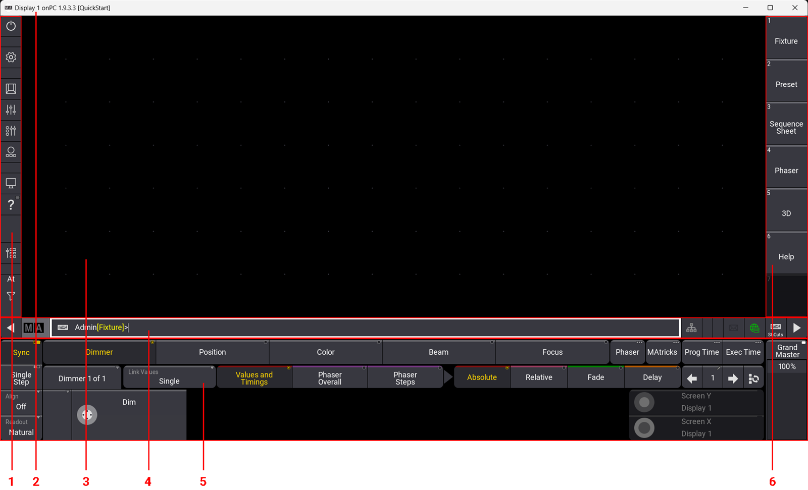
There are six different areas indicated in the picture above. The areas have different purposes:
- Control Bar - Very useful when using the grandMA3 onPC. It has shortcuts to different windows and menus.
- Title Bar - This is the Windows title bar (Mac OS has a similar title bar). It shows the display number, the software version, and the name of the show file.
- User-defined Area - This area is where you can create views with different windows.
- Command Line - This row has different indicators and buttons with quick access to different menus. The center part is the Command Line Input. Here you can write commands to the software.
- Encoder Bar - This area is often used to apply values to the different attributes of the fixtures. The right side has controls for the Grand Master for the console. On the full-size and light consoles, this area is on the letterbox screen 8.
- View Bar - This bar has buttons called ViewButtons, where we can store and recall different views.
The interface dynamically adjusts when you are using a grandMA3 onPC. The user-defined area can expand and contract based on the display size.
It can also be configured to hide some areas or scale the interface. This is done using the Configure Display pop-up. This can be accessed when the Menu selection pop-up is visible. Do this by clicking the gear icon (![]() ) in the control bar. Then click Configure Display in the smaller "Display" pop-up.
) in the control bar. Then click Configure Display in the smaller "Display" pop-up.
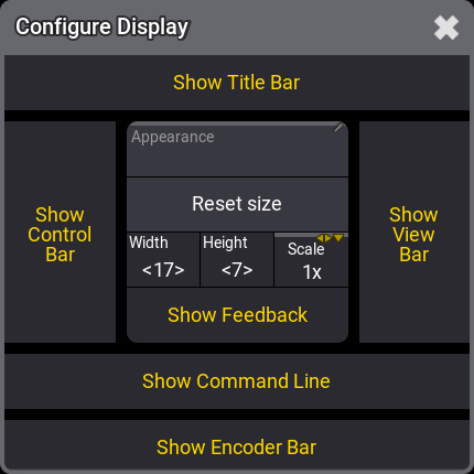
Here the different areas can be toggled On or Off. When something has a yellow text color, it is On or selected.
Width and Height define how many square fields the user-definable area has. Scale can be used to scale the entire interface visually.
Predefined Views
When we talk about a view, it is the set up of windows in the user-defined area. These views can be stored and recalled. They can be assigned to the buttons like the one in the View Bar on the right side of the interface.
If you change a view and you would like to keep the change. Then you simply store the view again.
A new show file has some predefined views that can be very useful.
Click the one called Fixture.
Depending on your display size, you might see a view that is cut off on the bottom or/and the right side. This is because the stored view is bigger in width and height than the current size of the user-defined area.
A thin brown frame indicates that the view is bigger. Scroll bars appear, allowing you to scroll to other parts of the view. If you have touch screens, then a three-finger touch and scroll also move the view inside the user-defined area.
Fixture Sheet
We are going to create our own view. So the first thing we need to do is to get an empty user-defined area.
Again we can use the Menu selection pop-up. Click the gear icon (![]() ) or press the Menu key.
) or press the Menu key.
All screens now have a small pop-up in the lower right corner. Click Delete This Screen in the small Display pop-up.
Now the user-defined area is empty again.
We want to create a window that shows us the dimmer values of the fixtures in our show. So far, we only have fixtures with dimmers.
Click the upper left corner in the user-defined area.
An Add Window pop-up appears. This pop-up gives access to all the different windows in the system. They are organized into different tabs. One of the tabs is called "All". This has all the windows in one alphabetically sorted list.
We need the window called Fixture Sheet. This can be found in the Common tab. Click Common and then Fixture Sheet.
Now we have a fixture sheet filling the entire user-definable area.
This window shows us the fixtures in rows and the attributes (in this case, maybe only the "Dimmer") in columns.
The Blinders fixture is collapsed and does not show the child fixtures. This can be changed by clicking the white triangle arrow either at the top of the left column or the arrow next to the Blinder name.
There might be a Universal Fixture in the list. Just keep ignoring this for now. I will explain it later in this chapter.
We can change how the window looks when we are only interested in looking at the dimmer values. This is done in the Settings for the window. All windows have an MA logo in the upper left corner. Click this to open the settings for the window.
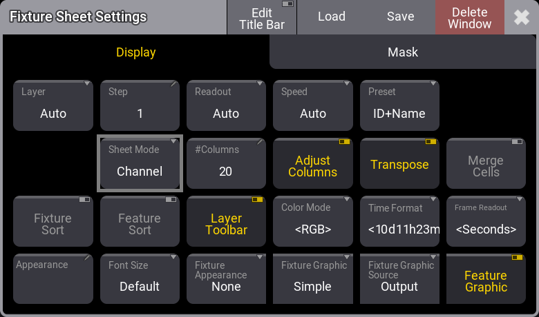
Different windows have different settings. Some are common settings, and some are individual for a specific type of window. The settings are often organized into different tabs. We want to change a setting called Sheet Mode. It is found in the Display tab. Click SheetMode until it says Channel.
The settings should look like this:
Now the Fixture Sheet is changed, and it only shows tiles with the ID and the dimmer value.
Close the settings by tapping the ![]() in the upper right corner of the settings pop-up.
in the upper right corner of the settings pop-up.
Looking at the fixture sheet, you might wonder, "Why are there two fixtures 1 in the sheet". The one in the lower right corner is the virtual universal fixture that the system automatically creates. It is not "Fixture" 1; it is "Universal" 1. The universal fixture contains some of the most generic functions in fixtures. All you need to do for now is ignore it and not worry about it.
This fixture sheet window is much bigger than needed, and we can adjust it to match our needs. The lower right corner of the window looks like this:  . This can be used to resize the window.
Click and hold the resize corner and move it to a new location in the user-defined area. Release the mouse button (or screen) on a location where the window looks nice to you.
Store the View
We want to store the new view on one of the ViewButtons on the right side.
Let us begin by clearing a button for our new view.
We need to press the 'Delete' key. If you use a grandMA3 onPC, then there is an on-screen version of the physical keys of the Command Area of the consoles. This can be opened by clicking the ![]() icon in the command bar on the left or by pressing F3 on a keyboard. It can be closed again by clicking the
icon in the command bar on the left or by pressing F3 on a keyboard. It can be closed again by clicking the ![]() in the upper right corner or pressing F3 again. I am going to write "press" a key. This might mean that you open this on-screen representation of the command keys and click the representation of the key. But I will write about them as if you had the physical keys on a console.
in the upper right corner or pressing F3 again. I am going to write "press" a key. This might mean that you open this on-screen representation of the command keys and click the representation of the key. But I will write about them as if you had the physical keys on a console.
So, Press Delete and then close the Command Area pop-up, and then click the top ViewButton on the right. Now the ViewButton should be empty.
Next is to store the current look of the user-defined area on the empty ViewButton.
Instead of pressing the 'Store' key, we will use the command line input.
Click the command line input where it says "Admin[Fixture]>". Now write Store, so the command line looks like this:
Now click the empty ViewButton.
This opens a Store View Options pop-up.
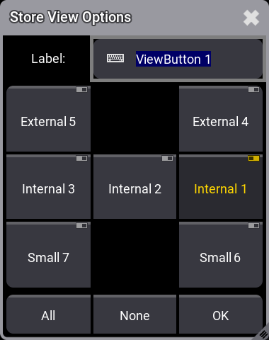
Here we can see that we are currently storing the windows on display "Internal 1" and we can give the view a name or label. Write Dimmer as the name/label and click OK.
The view is now stored on the button, and it can be recalled anytime by clicking the view button.
Command Line History
Another view that can be useful to have visible is the Command Line History window.
Often it can be an advantage to see how the console reacts to your input. The Command Line History window continually gives you a lot of information. It shows how the software interprets our user input and if the input is not understood or gives an error.
Do not be confused about all the information. We will go through it when needed.
Let us create the window.
When we made the fixture sheet, we clicked in the upper left corner, and the window took all the available space. Now we are going to try a different technique.
Click and hold below the fixture sheet and drag a square of the size you want the window to be. Now release the mouse/screen.
Now the Add Window pop-up appears again, and in the Common tab, click Command Line History.
Now you have a Command Line History window.
You can still adjust the size if you are not happy with the size you made.
A window can be moved around by clicking, holding the title bar, and dragging the window around. If there is not enough space, the window will resize automatically on the right and bottom sides.
Update the View
We are going to add one more element to the view.
In the area below the command line history, we need to create a new window. Click and drag the area below the window. In the Add Window pop-up, we need to click Data Pools and then Quickeys.
When we first create a pool, it is often empty and just has a lot of "containers" for objects or elements. Pools are often limited to only contain one kind of element. Sometimes we need to store into an empty pool element; other times, we edit an empty element to define what it should do.
Quickeys are virtual hardware keys that can be organized in a pool. Instead of us having to open the Command Section every time we need to press a key, we can create the key in the Quickey pool.
Let us create the first key in the pool. Right-click the first empty pool object where it says "1". This opens the Edit Quickey 1 pop-up. We need to edit the "Code" input. Clicking this opens a big pop-up with all the different hard keys. Click Store in the pop-up. This also changes the name of the quickey. Close the editor pop-up. Now we have an on-screen version of the 'Store' key. Once a quickey is created, it works exactly as a physical key. We explore pools more in chapter 6.
When you are happy with the windows' size, location, and look, you can store the view on the view button again.
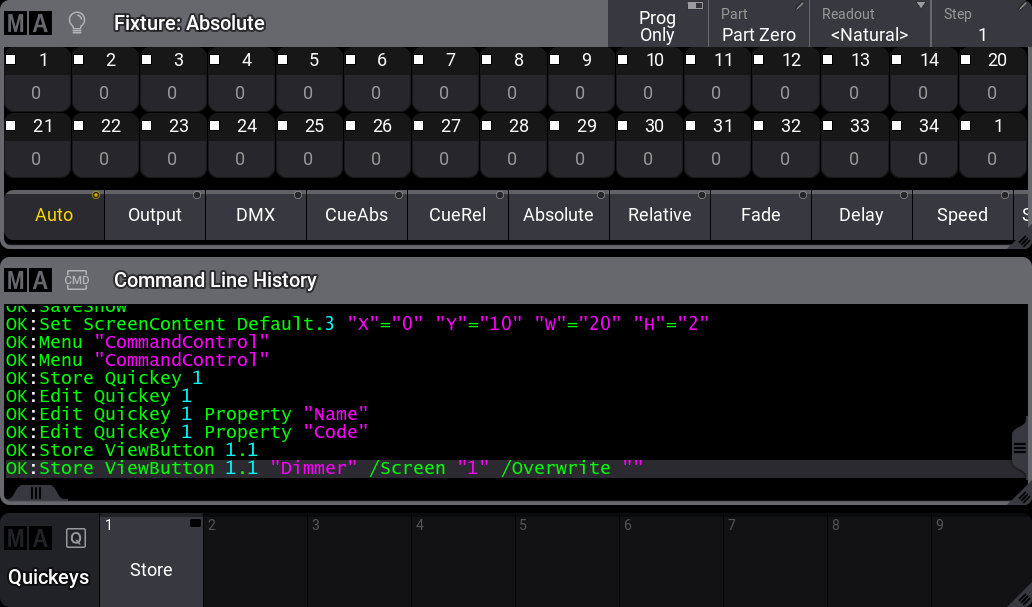
Click the new Store quickey and then tap the view button. Confirm the name and the store action by clicking OK in the Store View Options pop-up.
Here is my result. I have changed the #Columns option in the fixture sheet settings to 15. This makes the fixtures align nicely in the sheet.
You should save your show.
Recap
This chapter briefly introduced the user interface and the command line input.
We also looked at creating windows in the user-defined area and storing the windows, their settings, and their arrangement on a view button.
The manual has an entire section with details about the windows and view. It is called Windows, Views, and Menus.
The fixture sheet is described in detail in the Fixture Sheet topic.
The command line and the Command Line History window are described in detail in the Command Line topic.
And naturally, there is also a section about the Quickeys.
In the Next Chapter, we are going to control the dimmers.