

- grandMA3 User Manual
- grandMA3 Quick Start Guide
- 00 Welcome
- 01 New Show and Setup
- 02 First Patch
- 03 First View Setup
- 04 Control Simple Fixtures
- 05 3D Fixture Setup
- 06 Groups
- 07 Appearance
- 08 Scribbles
- 09 Macros
- 10 Store Cues and Use Executors
- 11 Add Moving Lights
- 12 Control Moving Lights
- 13 Presets
- 14 Phasers
- 15 Sequence with multiple cues
- 16 Network and How to Output DMX
- grandMA3 Quick Manual consoles
- grandMA3 Quick Manual processing units
- grandMA3 Quick Manual Nodes
- grandMA3 Quick Manual Nodes DIN-Rail
- grandMA3 Quick Manual onPC command wing XT
- grandMA3 Quick Manual onPC command wing
- grandMA3 Quick Manual onPC fader wing
- grandMA3 Quick Manual onPC rack-unit
- grandMA3 Quick Manual viz-key
- grandMA3 Quick Manual I/O Nodes
- Release Notes
New help version
The help version you selected belongs to an older software version. You may want to view the latest help version.
3D Fixture Setup
3D Window
The grandMA3 software has a virtual 3D stage area.
The fixtures we patched exist in this environment, and other elements can be imported to match the stage and set elements.
It is a visualization tool where the fixtures can be positioned to match the real-world positions, and the fixtures can be rotated to point in the correct direction.
You can create a new window to see the 3D stage area. The window is found in the Common tap in the Add Window pop-up. It is called 3D.
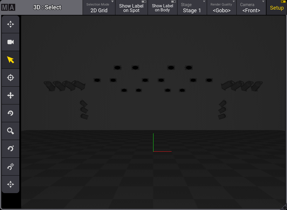
This is what it currently looks like:
![]()
When the fixtures are patched, they are positioned at the zero position. This is where we can see a green and red line in the image above. As a default, it is on the floor in the middle of the stage area.
We are looking at the stage area through a virtual camera. There are several default cameras, but for now, we are just gonna use the one called Front. You can see what camera we are using in the 'Camera' button in the title bar.
The toolbar on the left side of the window has different tools that allow for fixture selection and view manipulation. From the top they are:
 Zoom to Fit - moves the virtual camera to fit all elements.
 Camera Reset - moves the virtual camera to its default position.
 Select - for selecting fixtures or other objects.
 Follow - we are not gonna cover this function in this topic. It is used to point moving lights at the position you click in the window.
 Move - This moves the camera around.
 Rotate Center - This rotates the camera around the center (0,0,0) position.
 Zoom - Zooms in and out from the position clicked.
 Rotate Pivot - Rotates the camera around a set pivot point.
 Set Pivot - Sets the pivot point for the rotate function above.
 Fit Selected - Moves the camera to fit the selected fixtures.
If the window you created is less than six squares high in the user-definable area, then the menu is split into two columns.
Try out the different tools and get comfortable moving the camera around.
Did you notice that the fixtures appear to be under the floor?
This is because the fixture's insert point is usually its hanging point.
For this to be useful, we need to position and rotate fixtures to match our setup.
The 3D window has a mode called Setup. Setup is turned Off when you do not want to change the fixture position and rotation but simply want to use the window. Setup is turned On when you want to change the fixture setup. The mode can be changed by toggling the "Setup" button in the 3D windows title bar.
Turn the setup mode On.
Select fixture 1.
Now the encoder toolbar has changed to allow you to use the encoders to change the fixture position and rotation.
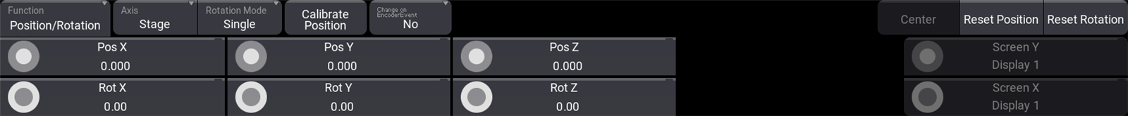
The 3D axes are X, Y, and Z. They can be positive or negative numbers. The X-axis is usually set up to be stage left and right. Stage right will be negative numbers if 0 is on the centerline. The Y-axis is usually downstage and upstage. Positive numbers are upstage. The Z-axis is the height. Positive numbers are typically above the floor.
The inner encoders move the fixture around, and the outer encoder ring changes the fixture rotation. Try moving and rotating the fixture. Notice that when you are changing one of the rotation values, it may also change the values for the two other rotation axis.
On the right side of the encoder bar, there are buttons to reset the fixture position and rotation.
The position and rotation values are actually a part of the patch information. Changing the values using the 3D window writes the values to the setup. If you are changing a lot of fixtures and you know the values, then it might be easier to make the changes in the patch.
Click the ![]() icon in the control bar (or Menu) and click Live Patch.
icon in the control bar (or Menu) and click Live Patch.
Live Patch is a version of the patch menu where you can make live changes that can be done without changing the show configuration. This means that you, for instance, cannot add or delete fixtures to the show, but we can change what DMX address a fixture is patched to. And we can change the fixture position and rotation.
The patch menu has two different column modes. They are Condensed and Full. Condensed only shows a few common columns. Full shows all the different columns and settings available for the fixtures. The mode can be changed by toggling the "Columns" button in the patch menu title bar. Change it to Full.
Now you can see all the different fixture settings that belong to the patch.
There are position and rotation columns for the fixture.
Change the numbers to match the following table. You can select multiple cells with lasso selection or by holding Ctrl on a keyboard while clicking cells.
|
FID |
Name | Type | Patch | X-Pos | Y-Pos | Z-Pos | X-Rot | Y-Rot | Z-Rot |
|---|---|---|---|---|---|---|---|---|---|
| 1 | Dim 1 | Dimmer - Mode 0 | 1.1 | -4.00m | -4.00m | 3.30m | 60.20 | -3.50 | -6.00 |
| 2 | Dim 2 | Dimmer - Mode 0 | 1.2 | -3.67m | -4.00m | 3.30m | 61.25 | -9.00 | -15.75 |
| 3 | Dim 3 | Dimmer - Mode 0 | 1.3 | -3.33m | -4.00m | 3.30m | 63.20 | -14.00 | -25.65 |
| 4 | Dim 4 | Dimmer - Mode 0 | 1.4 | -3.00m | -4.00m | 3.30m | 66.14 | -18.75 | -36.00 |
| 5 | Dim 5 | Dimmer - Mode 0 | 1.5 | 3.00m | -4.00m | 3.30m | 66.14 | 18.75 | 36.00 |
| 6 | Dim 6 | Dimmer - Mode 0 | 1.6 | 3.33m | -4.00m | 3.30m | 63.20 | 14.00 | 25.65 |
| 7 | Dim 7 | Dimmer - Mode 0 | 1.7 | 3.67m | -4.00m | 3.30m | 61.25 | 9.00 | 15.75 |
| 8 | Dim 8 | Dimmer - Mode 0 | 1.8 | 4.00m | -4.00m | 3.30m | 60.20 | 3.50 | 6.00 |
| 9 | Dim 9 | Dimmer - Mode 0 | 1.9 | -4.00m | 0.00m | 2.80m | 16.00 | -45.00 | 0.00 |
| 10 | Dim 10 | Dimmer - Mode 0 | 1.10 | -4.00m | 0.00m | 2.40m | 16.00 | -57.50 | 0.00 |
| 11 | Dim 11 | Dimmer - Mode 0 | 1.11 | -4.00m | 0.00m | 2.00m | 16.00 | -70.00 | 0.00 |
| 12 | Dim 12 | Dimmer - Mode 0 | 1.12 | 4.00m | 0.00m | 2.80m | 16.00 | 45.00 | 0.00 |
| 13 | Dim 13 | Dimmer - Mode 0 | 1.13 | 4.00m | 0.00m | 2.40m | 16.00 | 57.50 | 0.00 |
| 14 | Dim 14 | Dimmer - Mode 0 | 1.14 | 4.00m | 0.00m | 2.00m | 16.00 | 70.00 | 0.00 |
| 20 | Blinders | Grouping | |||||||
| 21 | Blinder 1 | COB - Blinder 2x100w - 1 ch | 1.15 | -2.00m | 0.50m | 4.70m | -73.00 | 0.00 | 0.00 |
| 22 | Blinder 2 | COB - Blinder 2x100w - 1 ch | 1.16 | -1.00m | 0.50m | 4.70m | -73.00 | 0.00 | 0.00 |
| 23 | Blinder 3 | COB - Blinder 2x100w - 1 ch | 1.17 | 1.00m | 0.50m | 4.70m | -73.00 | 0.00 | 0.00 |
| 24 | Blinder 4 | COB - Blinder 2x100w - 1 ch | 1.18 | 2.00m | 0.50m | 4.70m | -73.00 | 0.00 | 0.00 |
| 25 | Blinder 5 | COB - Blinder 2x100w - 1 ch | 1.19 | -3.50m | 2.00m | 4.20m | -73.00 | 0.00 | 0.00 |
| 26 | Blinder 6 | COB - Blinder 2x100w - 1 ch | 1.20 | -2.50m | 2.00m | 4.20m | -73.00 | 0.00 | 0.00 |
| 27 | Blinder 7 | COB - Blinder 2x100w - 1 ch | 1.21 | -0.50m | 2.00m | 4.20m | -73.00 | 0.00 | 0.00 |
| 28 | Blinder 8 | COB - Blinder 2x100w - 1 ch | 1.22 | 0.50m | 2.00m | 4.20m | -73.00 | 0.00 | 0.00 |
| 29 | Blinder 9 | COB - Blinder 2x100w - 1 ch | 1.23 | 2.50m | 2.00m | 4.20m | -73.00 | 0.00 | 0.00 |
| 30 | Blinder 10 | COB - Blinder 2x100w - 1 ch | 1.24 | 3.50m | 2.00m | 4.20m | -73.00 | 0.00 | 0.00 |
| 31 | Blinder 11 | COB - Blinder 2x100w - 1 ch | 1.25 | -2.00m | 3.50m | 3.70m | -73.00 | 0.00 | 0.00 |
| 32 | Blinder 12 | COB - Blinder 2x100w - 1 ch | 1.26 | -1.00m | 3.50m | 3.70m | -73.00 | 0.00 | 0.00 |
| 33 | Blinder 13 | COB - Blinder 2x100w - 1 ch | 1.27 | 1.00m | 3.50m | 3.70m | -73.00 | 0.00 | 0.00 |
| 34 | Blinder 14 | COB - Blinder 2x100w - 1 ch | 1.28 | 2.00m | 3.50m | 3.70m | -73.00 | 0.00 | 0.00 |
When the numbers match, you can close the patch menu and accept the changes if the software asks.
Now the fixtures are positioned and rotated, and the 3D window should look something like this:
Try to turn on the fixtures to see the light from the fixtures and try to move the camera around to see it from different positions.
When you are happy, remember to turn the 3D window "Mode" back to Standard by turning Off the Setup button. You can store this as a new view or store it on top of the default "3D" view.
The 3D window has a lot of different settings that allow you to adjust the window to match your wishes. For instance, it can be set up to have priority and run on a grandMA3 onPC on a powerful graphics computer, giving you high-quality real-time visualization. Or the quality can be scaled down to run on a console, where the user interface and cue control are prioritized.
For now, we are just gonna use it with the default settings.
Recap
In this chapter, we looked at the 3D window and positioned the fixtures in the 3D virtual space.
If you want to learn details about the 3D window, read the 3D Window topic.
The Position Fixtures in the 3D Space topic explores fixture positioning in more detail.
In future chapters, we will add more interesting fixtures to our patch and 3D space.
The next chapter, however, is about groups.