

- MA Network Switch
- Introduction
- Intended Use
- Dangers caused by Electric Current
- General Safety Instructions
- System Requirements
- SFP Transceiver Compatibility
- Device Overview
- Front Panel
- Rear Panel
- LED Indicators
- Factory Defaults
- First Steps
- Unpack the Device
- Install Mini-GBIC (SFP)
- Installation in a Rack
- Connect the Hardware
- Set the IP Address on the PC
- Access the Web Interface
- Display Navigation
- Groups View
- Name View
- Workload View
- LAG View
- Reset View
- Ports / Groups
- Change Port Description
- Assign Groups to Ports
- Edit LAGs
- Edit RSTP
- Edit Speed Setting
- Change Group Name
- Edit IGMP Snooping
- Edit IGMP Querier
- Edit Unknown Flooding
- Change VLAN ID
- Presets / Filters
- Assign Presets to Ports
- Apply Filters to Ports
- Create New Presets
- Update Presets
- Create New Filter
- View Filters
- Delete Presets
- Delete Filter
- General Settings
- Change Name
- Change ID
- Change DHCP Client
- Change IP Address
- Change Subnet Mask
- Change Default Gateway
- Change SNMP Status
- Change Password
- Update Firmware
- Fallback to Backup Firmware
- Get Switch Configuration
- Edit Port Mirroring
- Upload Switch Configuration
- Reset Settings
- Web Interface and grandMA2
- Specifications
- Support
- Glossary
- Introduction
Version 3.9
Install Mini-GBIC (SFP)
Table of contents of this topic
The MA Network Switch comes with up to four SFP cages. These cages accept mini-GBIC transceivers.
Two are at the rear panel, port 9 and 10. Two are inside the MA Switch.
For information on the compatibility see SFP Transceiver Compatibility.
To install mini-GBIC transceivers inside the switch at port 11 and port 12, call your local distributor.
Install mini-GBIC at port 9 and 10
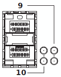
1. Remove the mini-GBIC from its protective packaging.
Be aware of the insertion direction.
Port 9 must have the bail wire delatch on the top.
Port 10 must have the bail wire delatch at the bottom.
Port 9 must have the bail wire delatch on the top.
Port 10 must have the bail wire delatch at the bottom.
2. Install the mini-GBIC into the slot 9 or 10 at the rear panel, until the mini-GBIC clicks into place.
For detailed description of your mini-GBIC transceiver, refer to the transceiver manual.
Remove mini-GBIC from port 9 and 10
- Open the ball wire delatch to disengage and remove the mini-GBIC transceiver.
- Replace the protective plastic cover on the mini-GBIC.
The mini-GIBC is removed from the port.