
- dot2 User Manual
- dot2 Quick Start Guide
- dot2 3D
- Install and Uninstall
- System Requirements
- Installation
- Uninstall dot2 3D
- First Steps
- Hardware Connection
- Create session and connect 3D
- Data Management
- Master/Slave
- Coordinate system
- Program Surface
- Menu Bar
- File Menu
- File - Settings
- Edit
- Functions
- Tools
- View
- Help
- File Menu
- Tool Bar
- Main Windows
- Stage View
- Mouse + Keyboard Actions
- Arrangement of Objects (Align Objects)
- Duplicate (copy 3D Objects)
- 3D Objects
- Assets (Information Window)
- Properties
- Media Database
- Materials
- Video Player
- Moving Paths
- Sessions
- Status Bar
- Window Layout
- Menu Bar
- Fixture Types
- 3D Modeling and Import
- 3D Models Principles
- Parameters
- Axes
- Rotation Axes
- Linear Axes
- Beam of Light
- Automated Import
- Assigning of Models to Fixture Types
- Checklist for 3D Modeling
- Creation of a 3D Model
- Keyboard Shortcuts
- dot2 3D FAQ
- Install and Uninstall
- dot2 Release Notes
Version 1.9
Creation of a 3D Model
3D objects can be created with 3D CAD programs.
The amount of polygons affects the performance because for each polygon the projection has to be calculated.
The lower the number of polygons the better is the frame rate.
dot 2 3D supports the following formats for 3D objects:
• .3ds - Format for drawing 3 dimensional objects
Note the following regulations:
- The orientation of the object should fit
- Normals have to be organized correctly
- UV coordinates for the textures have to be setup correctly
- The orientation of the object should fit
- Normals have to be organized correctly
- UV coordinates for the textures have to be setup correctly
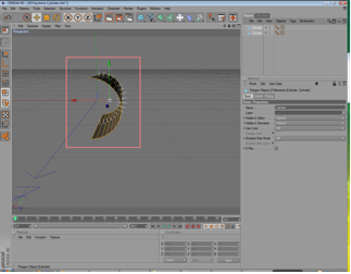
The following example shows the creation of a halved cylinder, created with 'Cinema 4D’:
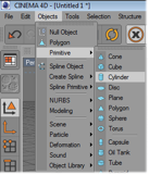 |
Insert an object of type 'Cylinder’ |
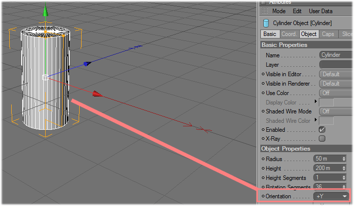 |
Set the orientation to 'Y+’. For a correct visualization in dot2 3D is the depth, Y the vertical and X the horizontal axis |
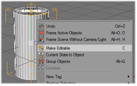 |
Make the object editable |
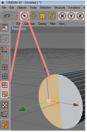 |
Select not used polygons… |
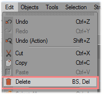 |
and delete them. |
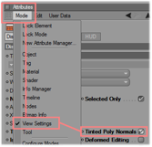 |
Set the visibility of normal on. |
|
|
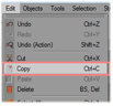
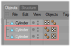
The next copy steps are only necessary if the object should be visible from both sides. Therefore it is duplicated and the normals are set in both directions. Copy the object… |
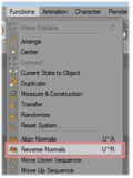 |
And reverse the normals of the copy. |
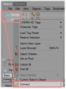 |
Select both cylinder objects and connect them to one new cylinder. |
 |
The old cylinder objects can be deleted. |
 |
Now you can see two objects with normals in both directions |
 |
Check the orientation of the resulting object. |
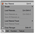 |
Insert a new material for the texturing. |
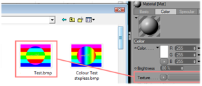 |
Assign an image to the texture and the material to the object (Mind the restriction of max. 8 characters + extension for the image name!). |
|
|
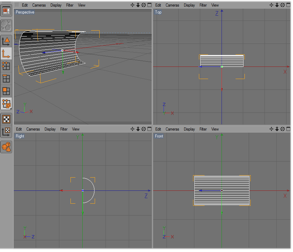
Adjust the texture mapping parameter. |
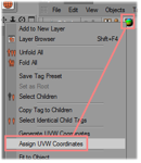 |
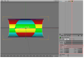
Assign the UV coordinates for the texture mapping. |
|
|
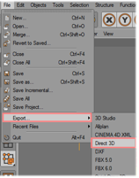
Export the object to 3D Studio format (.3ds).Objects created in this way can be added via the import tool. |
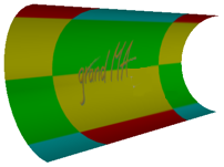 |
The resulting 3D Object looks like this. |