

- grandMA2 User Manual
- grandMA2 Quick Start Guide
- MA 3D
- MA VPU
- Introduction
- Help from MA technical support
- System requirements
- For your Safety
- Functions and Features
- Transition from grandMA video to MA VPU
- Teaser Mode
- Comparison VPU plus / VPU basic / VPU light
- Main Features
- Installation and Maintenance
- Startup
- Software update
- Service Packs
- Update of Fixture Types
- Backup
- Handling backups with the VPU
- Start Acronis on VPUs with serial Numbers up to # 86 on
- Start Acronis on VPUs with serial Numbers from # 87
- Restoring an image with Acronis
- Storing an image with Acronis
- Backup the VPU content after shipment
- Access VPU via Network
- Version of grandMA desk or grandMA onPC (off-line)
- IP Addresses
- IP Address of the PC
- Art-Net IP Address
- EDID Manager
- CITP / MSEX Protocol
- Installation and Maintenance
- Communication with the grandMA Desk Series
- Connection with the grandMA desk
- Connection with the grandMA onPC (off-line) software
- Connection States
- Data Management
- Master slave
- Principle function diagram
- Layer Properties
- Layer Reference
- Virtual Outputs
- Virtual Output: Configuration of a TripleHead2Go Digital Port
- Predefined Constellation
- Several MA VPU applications in one grandMA show
- Quickstart with grandMA2
- Program surface
- Internal Touch-Screen VPU plus
- Internal Screen VPU light
- Menu Bar
- File...
- View...
- Render...
- Help...
- Toolbar
- Status Bar
- Preview
- Multi Preview
- Content Editor
- Content: Image Pool (I-Pool)
- Content: Text Ticker
- Content: Eff1 Type...Eff4 Type
- Content: 3D Objects
- Content: Mask
- Warper
- Warper Fullscreen View
- Warper Basic Operation
- Warping
- File Browser
- Features Attributes and Functions
- Order of Effect Execution
- Softedging
- Keystoning
- Pixel Mapper
- VPU - Pixel Mapper Graphical View
- Pixel Mapper Toolbar
- Pixel Mapper Editor
- VPU - Pixel Mapper Grid View
- Console - VPU Pixel Mapper View
- VPU - Pixel Mapper Graphical View
- Creation of customized 3D Objects
- Content Specifications
- Rovi Total CodeStudio for converting your content into MPEG2
- Hap Content Converter
- Warnings
- Keyboard Shortcuts
- Supplement MA Lighting
- Intended use
- Data
- Symbols and warning labels
- LIMITATIONS
- Transport
- General Safety Instructions
- IMPORTANT SAFETY INSTRUCTIONS
- Electric shock warning on the rear of the grandMA
- Safety and Environment
- Quickstart Connect VPU plus
- Quickstart Connect VPU light
- Switching the apparatus On/Off
- Maintenance
- Conformity
- Introduction
- Release Notes
New help version
The help version you selected belongs to an older software version. You may want to view the latest help version.
Warper Basic Operation
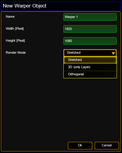 |
If a new warper object is added you can define the properties of the object in the upcoming dialog. Using the warper object on a layer: |
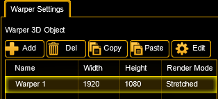 |
In the 'Warper Settings’ you can define the Warper object. It is handled by the VPU like the other 3D objects but it only has 2 dimensions X and Y. In prior versions the calculation of UV mapping referred to the width and height of the parent warper 3D object. Now the width and the height of a texture can be defined as base values of the calculation of the corresponding UV E.g. a warper object has a dimension of 1920 x 1080 which also fits the resolution of the output. The content has a resolution of 7680 x 1080 (4 times full HD). In this example the warper object is used on a layer and shall "grab" the third full HD space from the texture using the UV mapping. For this case the UV mapping is: U from 3841 to 5760 of 7680 and V from 1 to 1080 of 1080. The UV parameters are based on pixels and are scaled to one. If you have a texture with a resolution of full HD, enter the parameters from 1 to 1920. All position parameters of the warper are pixel based and scaled to zero. Position 0,0 corresponds to the top left of the screen. |
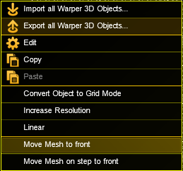
Warper 3D objects can contain several meshes. These meshes divide the projection area into several parts that are defined in the window 'Warper Meshes’. E.g. if your projection area is only one big bended plane you only need one mesh. If the area is splitted into different objects it favorable to use different meshes for these objects E.g. if the projection plane is covered with a box you can define a separate mesh for this box, put this box in front position and edit the characteristics.
| Meshes even can overlap. To define the order use the context menu: | |
 |
 |
| If a Warper 3D object is created a dialog comes up to describes the mesh: | |
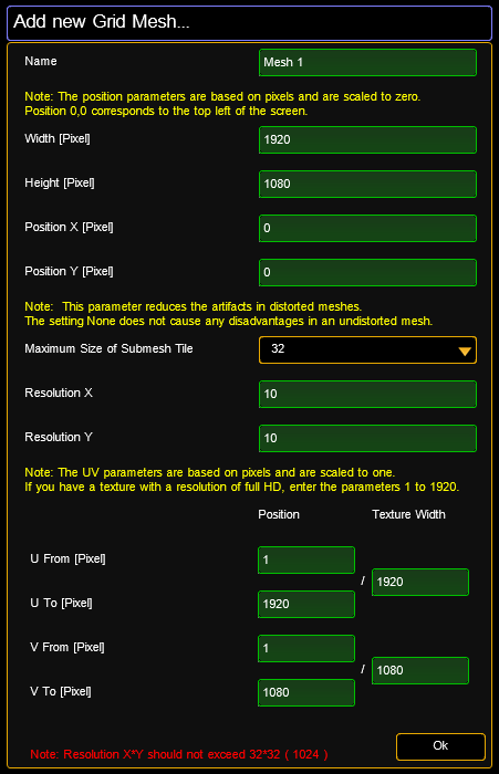 |
All coordinates refer to the origin 0,0 in the upper left corner. Maximum Size of Submesh Tile: Resolution X/Y: Describes the grid resolution of the mesh. |
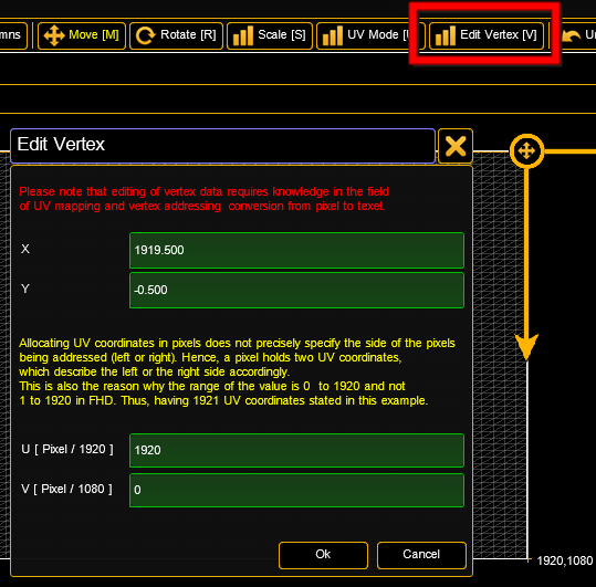 |
The UV mapping of a warper mesh can be edited graphically. A mesh now can also be rotated and scaled using the arrow keys. Vertex data of a mesh can be edited numerically. The vertex position as well as its UV coordinates can be modified. |
| Meshes can be edited always via a doubleclick into the graphic view on the mesh or the mesh list table. | |
|
Example: The projection plane is divided into 4 even planes: |
|
 |
This Warper 3D Object is tiled into 4 meshes: - upper left - upper right - lower left - lower right. |
| Placement of the 4 meshes: | |
 |
The output image can be placed on the meshes. The coordinates of the output image are described via the U/V coordinates. The origin (0,0) of the U/V coordinates is in the upper left corner of the image. |