

- grandMA2 User Manual
- grandMA3 Mode2
- grandMA2 Quick Start Guide
- grandMA2 Quick Manual onPC solutions
- MA 3D
- MA VPU
- Introduction
- Help from MA technical support
- System requirements
- For your Safety
- Functions and Features
- Transition from grandMA video to MA VPU
- Teaser Mode
- Comparison VPU plus / VPU basic / VPU light
- Main Features
- Installation and Maintenance
- Startup
- Software update
- Service Packs
- Update of Fixture Types
- Backup
- Handling backups with the VPU
- Start Acronis on VPUs with serial Numbers up to # 86 on
- Start Acronis on VPUs with serial Numbers from # 87
- Restoring an image with Acronis
- Storing an image with Acronis
- Backup the VPU content after shipment
- Access VPU via Network
- Version of grandMA desk or grandMA onPC (off-line)
- IP Addresses
- IP Address of the PC
- Art-Net IP Address
- EDID Manager
- CITP / MSEX Protocol
- Installation and Maintenance
- Communication with the grandMA Desk Series
- Connection with the grandMA desk
- Connection with the grandMA onPC (off-line) software
- Connection States
- Data Management
- Master slave
- Principle function diagram
- Layer Properties
- Layer Reference
- Virtual Outputs
- Virtual Output: Configuration of a TripleHead2Go Digital Port
- Predefined Constellation
- Several MA VPU applications in one grandMA show
- Quickstart with grandMA2
- Program surface
- Internal Touch-Screen VPU plus
- Internal Screen VPU light
- Menu Bar
- File...
- View...
- Render...
- Help...
- Toolbar
- Status Bar
- Preview
- Multi Preview
- Content Editor
- Content: Image Pool (I-Pool)
- Content: Text Ticker
- Content: Eff1 Type...Eff4 Type
- Content: 3D Objects
- Content: Mask
- Warper
- Warper Fullscreen View
- Warper Basic Operation
- Warping
- File Browser
- Features Attributes and Functions
- Order of Effect Execution
- Softedging
- Keystoning
- Pixel Mapper
- VPU - Pixel Mapper Graphical View
- Pixel Mapper Toolbar
- Pixel Mapper Editor
- VPU - Pixel Mapper Grid View
- Console - VPU Pixel Mapper View
- VPU - Pixel Mapper Graphical View
- Creation of customized 3D Objects
- Content Specifications
- Rovi Total CodeStudio for converting your content into MPEG2
- Hap Content Converter
- Warnings
- Keyboard Shortcuts
- FAQ and Troubleshooting
- Supplement MA Lighting
- Intended use
- Data
- Symbols and warning labels
- LIMITATIONS
- Transport
- General Safety Instructions
- IMPORTANT SAFETY INSTRUCTIONS
- Electric shock warning on the rear of the grandMA
- Safety and Environment
- Quickstart Connect VPU plus
- Quickstart Connect VPU light
- Switching the apparatus On/Off
- Maintenance
- Conformity
- Introduction
- Release Notes
Pixel Mapper Editor
| Library | ||
|---|---|---|
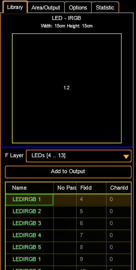 |
Library: In the library tab on the left side you can select each fixture layer of the setup that contains fixtures you want to use. Select these fixtures and press the Add to Output button. A pop-up will ask, which axis is used: any combination can be done and each axis can be inverted. This is used to "transfer" the position from the 3D stage view environment into the 2D footprint in the VPU. This process is comparable to the option "take Camera" in the Layout View, but with fixed positions. |
|
| Area / Output | Area/Output: The general output of MA VPU is done via Ethernet protocols like Art-Net instead of the graphic card of the PC. Therefore the physical dimensions of the LED matrix (Area) and the number of pixels (Output) can be set: |
|
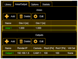 |
Areas: Here the physical width and height of the LED matrix is determined. This must not be conform to the whole size of the LED Panels. So e.g. only sub ranges of the general view of the LED Panels can be set. To set the dimensions of an area, select the area and press Edit. The area is defined in n * m cm. Outputs: List of the outputs. Every pixel mapper output can contain several fixtures. Network settings can be defined seperately for every output. |
|
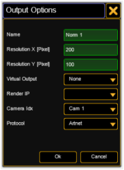 |
Virtual Output: The output of the Pixel Mapper can be mapped as a virtual input of a layer. In this case the render IP is suppressed. Render IP: Set which MA VPU shall render the output by choosing its MA-Net2 IP. Camera Idx: Index of the camera used for this output. Delay: To each graphic output or Pixel Mapper output a delay can be assigned. The value accords to the refresh rate of the output (not of the video clip). For each output of the pixel mapper a delay from up to 8/30 Seconds can be set (refresh rate for DMX signal is 30/s). Protocol: Choose between Art-Net, sACN or MA-Net2 protocol. sACN is comparable to Art-Net but allows the multicast option to reduce network traffic. (American National Standard E1.31.2009) Priority: Set a priority for the output regarding to the playback priorities of the grandMA2 desk. Default is "low". |
|
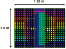 |
Example: The physical dimensions of the source picture must not confirm to the whole size of the panels. The LED panels can display, for example only a sub range of the whole output. In this example the area size is 1,25m x 1,0 m with 25 x 20 pixel. There are only 16 panels used (5 x 5 LEDs). The middle stripe is not equipped with LED panels and is not used. |
The Pixel Mapper works best if the resolution X of the output can be divided by 8.
Start Universe Art-Net and sACN:
To each output of the Pixel Mapper a start universe can be assigned for Art-Net or sACN.
This function is necessary to adress control data via Art-Net or sACN independent from their patch addresses:
sACN:
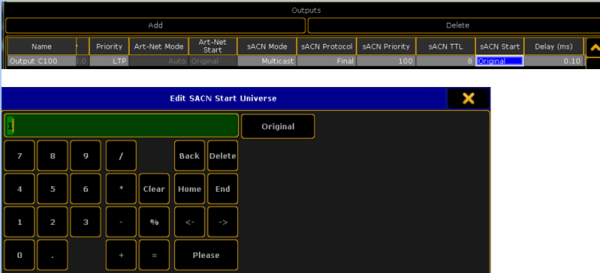
If the start universe is not changed by the operator, data will be sent as patched in the desk.
If a start universe is defined here, the lowest patched universe of the corresponding Pixel Mapper output will be used.
Other patched universes gear to this start universe.
Example: 4 LED panels are patched to universe 11, 12, 13 and 20 and the sACN start universe is set to 1.
Then control data are sent on universe 1,2,3, and 10.
The user can choose a start universe (as defined in sACN specs.) between 1 and 63999.
If the user sets the "Original" button, DMX data will be send again as patched in the desk.
Art-Net:
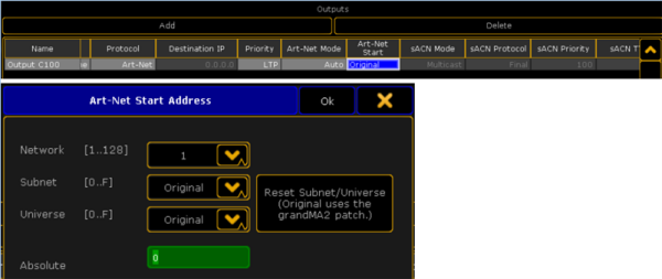
Same principle with Art-Net. In this case with Art-Net specific entries of the start universe.
If the user sets the "Original" button, DMX data will be send again as patched in the desk.
| Options | ||
|
Network: Adjustment: Render: |
||
| Statistic | ||
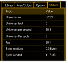 |
Statistic: This tab offers information about the used universes, DMX channels and the performance. |