

- dot2 User Manual
- dot2 Quick Start Guide
- 1 - Introduction
- 2 - Physical setup and layout
- 3 - Create a new empty show
- 4 - Adding and patching dimmers
- 5 - Controlling dimmers
- 6 - Fixture view
- 7 - The programmer
- 8 - Making and working with groups
- 9 - Store a cue and play it back
- 10 - Making more cues in the cue list
- 11 - Adding LED fixtures
- 12 - Working with colors
- 13 - Creating presets
- 14 - External screen
- 15 - Adding moving lights
- 16 - Controlling moving lights
- 17 - Making more groups and Presets
- 18 - More about cues and playback
- 19 - A look at Blind, Preview and DMX tester
- 20 - Fun with macros
- 21 - Building chasers
- 22 - Building dynamic effects
- 23 - Connect to onPC, 3D, Wings and Nodes
- 24 - Happy programming
- dot2 3D
- dot2 Release Notes
Getting Started Guide - Physical setup and layout - how to connect stuff and what's what
You should always place your console on a flat and stable surface. It's also a good idea to avoid a dirty and dusty environment - yeah I know, not often a possibility, but it's recommended anyway .
The back
The back panel looks like this (on a dot2 core):
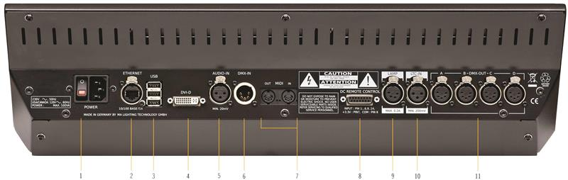
There's a lot of different connectors on the back of the console. For this tour we'll need to connect power (the connector at number one) and I would suggest that you connect a USB keyboard to one of the USB connectors at number three. You should also connect an external screen (connector number four). The best is a screen with touch function. If you don't have a touch screen, then you should connect a mouse. Both are connected to the USB connectors at number three. That's the devices we need for the beginning of this guide. Later we'll look at connecting the console to a network (using the Ethernet connector at number two).
When you have connected the needed devices, then you can press the power button (at number one) to turn on the console - remember to connect it to a suitable power source.
The following is a short description of all the connectors on the back:
- Power switch and connector - Here you can connect the power cord and turn on or off the console.
- Ethernet connector - This is for connecting to a network.
- 3 x USB connectors - for USB memory sticks, touch screen, keyboard & mouse, etc. Output for each USB–Port: max. 140 mA/5 V
- DVI-D connector - for an external digital screen. You can't use a DVI to VGA adaptor. It's for digital screens only.
- Balanced Audio in - this is a balanced mono audio input for sound trigger functionality.
- DMX input - this DMX input is used for DMX remote control only.
- MIDI in and out - the MIDI can be used also as a remote control and for MIDI Time Code.
MIDI OUT is also automatically a MIDI THRU. Signals sent via MIDI OUT have a higher priority than that sent via the MIDI THRU.
- DC Remote Control - this is for contact closure remote control.
- Lamp connector - this if for the console goose neck lamp. Please only use original dot2 lamps.
- LTC connector - this is used for SMPTE Time Code.
- 4 x DMX out - here you can get universe 1 to 4 out of the console.
The front
The front of a dot2 core looks like this:

Throughout this guide I'll mention different areas of the console.
This is a short walk-through of the different ares:
- Command section - This is where you have access to most of the functions on the console using keys.
- Encoders - The encoders are used to select and change values and options. You can press an encoder to confirm your current choice and sometimes open other windows. The functions of the encoders changes throughout the different sections of the console. The current function and values can be viewed on the screen above them (indicated with number 10 - Screen 1).
- Main Executor - This is the main executor section. Here you'll most likely put your primary cue list.
- Executors with faders - These executors can also have cue lists, but they could also have chasers, group masters and other functions. There's one key under the fader with this symbol
 . This is the executor GO key (This is unfortunately called "Button 1" in some view). The one below this have this symbol
  , this is the executor Flash key (this is unfortunately called "Button 2" in some view). The executors are numbered from the Main executor (number three) to the left. So the one closest to the Main executor is executor number 1.
 - Executors without faders - There are two rows of extra executors above the ones with faders. They are independent of each other. They are only executor GO keys - . The functionality don't have to be Go. They are also numbered from the Main executor and to the left. The top row begins with number 101 and the next row begin with 201. If you press and hold the
 key then you can see the numbers at the bottom of the screen above them (number 11 - Screen 2). Moving forward I'll just use the executor numbers.
 - Page keys - Pressing these keys you can change the page numbers for your executors. This allows you to organize your show onto different pages. Active executors are always visible and will stay "on top" when you change page. We'll have a look at this later. You can't change the page for the Main executor.
- Grand Master - The grand master fader allows you to pull down the intensity of your output. The B.O. key will take the output to zero as long as it's pressed. If it flashes then, your grand Master fader isn't at 100%.
- Level wheel - You can change the intensity of your selected fixtures using this level wheel.
- Menu keys - These three keys gives you access to the three main menu sections of the console. A lot more about this in the next chapters.
- Screen 1 - This screen changes content dynamically with your work. At the bottom of the screen you can always see the function and values of the encoders below. There will also be a command line input. On the right side of the screen you'll be able to select different functions for the fixtures (when we add some).
- Screen 2 - This screen allows you to view and select different things and functions. We'll talk a lot more about this one.
If you have a dot2 XL-F or dot2 XL-B, you have some more executors and you have another screen (screen 3) on the left side. Please press the key to see the executors numbers.
Ok that's what it looks like. Let's start doing something - Next chapter please.